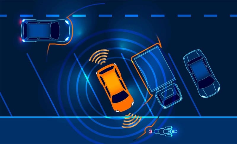
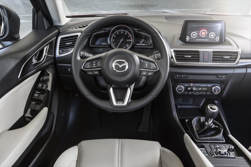
 With summer coming to an end and frost in the forecast, there’s no better time to add a remote starter to your car, truck or SUV. Most of us know that our remote starter systems can also control the power locks in our vehicles, but many systems are full of additional advanced features that add convenience and improved comfort to our vehicles. Let’s look at 10 things you may not know your remote starter can do.
Before we dive in, we should let you know that the functions we are going to describe are dependent on the model of remote starter you choose, the remote you choose and the vehicle you own. Talk to your local mobile enhancement retailer about these options and any associated costs.
1. Rear Window Defroster Activation
You may know about this one, since it is probably the number-one option people add to their remote starter systems. If the interior of your vehicle is below a certain predetermined temperature when the car is remote started, the remote starter system can automatically activate the rear window defroster to help you see clearly when it is time to go. Even a few minutes of warm-up time can make clearing the rear window quick and easy before you get in the car. Likewise, some cars have sideview mirror defrosters tied to the rear window heating system for added convenience.
2. Trunk/Hatch Release
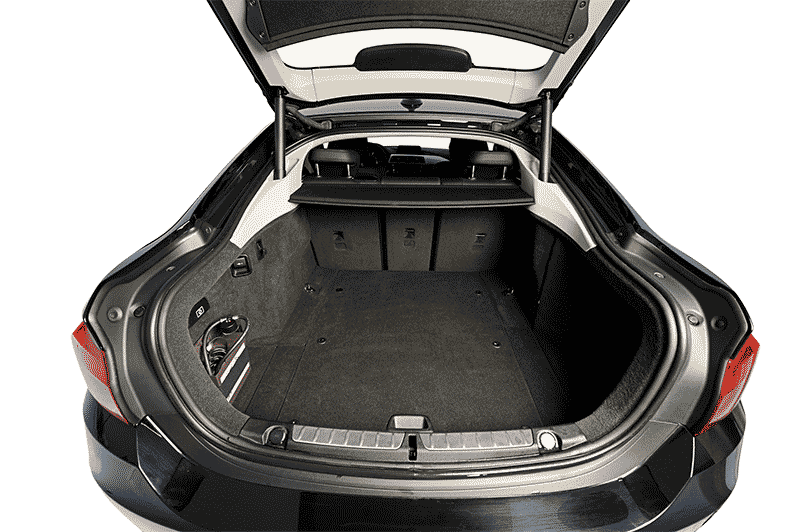 Trunk or hatch release from a multi-button remote isn’t all that exciting, but it sure is convenient. If your vehicle doesn’t happen to have a trunk release button, ask your retailer about adding a solenoid. Yep, they can add the power trunk function to most vehicles.
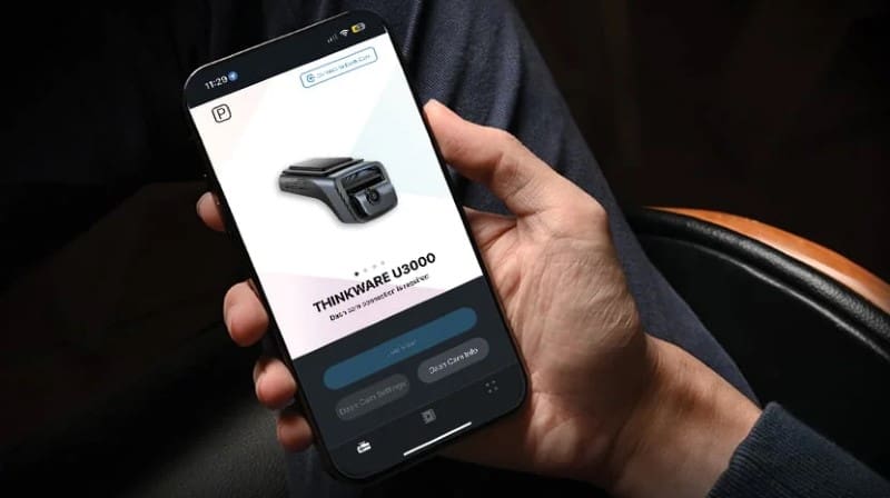
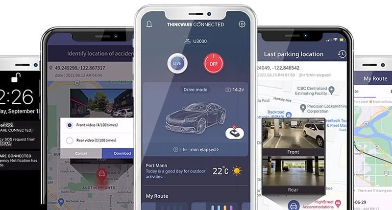
3. Remote Start Your Car from Your Phone or Apple Watch
Several different options for telematics systems use an application on your iPhone or Android phone to lock, unlock and remote start your vehicle. Several of these apps are compatible with the Apple Watch, so you can press a button on your wrist to warm up your vehicle.
4. Start Automatically When the Weather is Cold or Hot
Many remote starter systems can be programmed to start automatically when the internal vehicle temperature drops below or rises above a predetermined temperature. Temperature start will ensure the temperature does not get too extreme.
5. Start Every Few Hours or Daily
Some systems offer the ability to start every few hours. When the temperature outside is frigidly cold, keeping some warmth in the engine, fuel system and coolant is useful. You can toggle this function from most remote controls.
6. Protect Your Vehicle
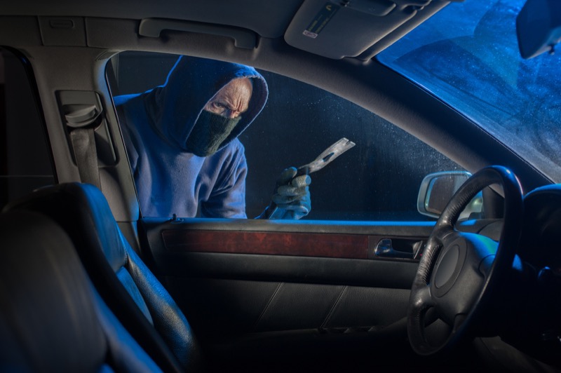 A remote starter system can often be upgraded with security system functions. Starter kill, a siren and a multi-stage shock sensor help to ensure that would-be thieves are sent packing if they start messing with your vehicle. If you have a two-way remote control or a smartphone telematics system, you will be alerted as soon as the alarm goes off.
7. Control Power Sliding Doors
If you drive a van with motorized sliding side doors, your mobile enhancement retailed can often add control for those into your remote started. Most system includes one or two auxiliary outputs that can be used to open or close doors or power tailgates.
8. Control Power Windows and Sunroof
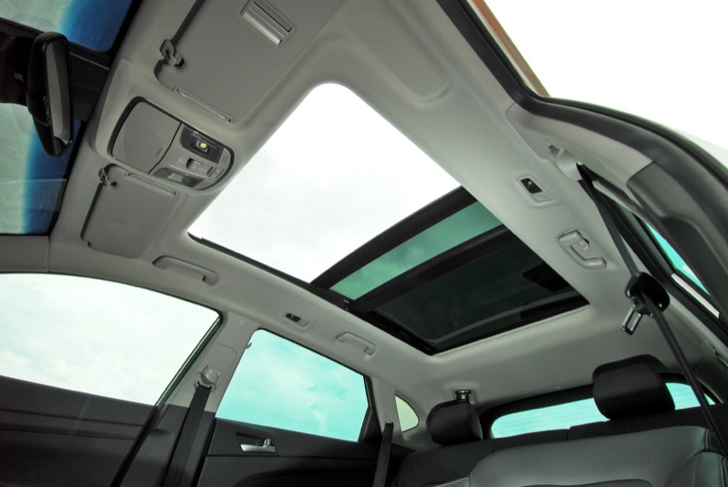 Remote starters are just as useful when the weather is hot as they are when it’s cold. In many applications, we can add a module that allows you to roll your windows up or down, and open or close your sunroof. Imagine arriving at your destination with your windows down and sunroof open. You get out of the vehicle and start walking away. When you press the lock button on your remote, all the windows roll up, and the sunroof closes automatically. It’s not only a convenient feature, but it’s kinda cool, too!
9. Control Multiple Vehicles
 If there are two vehicles in your family with similar remote starter systems, you can often control both from a single remote control. Depending on your remote, you can toggle between vehicles, or control the second vehicle using an extra button press before the function you want to activate.
10. Extend the Life of Your Engine
 Perhaps this should be the first item, because it’s one of the most important features a remote starter offers. Most people think they are buying a remote starter to make the vehicle more comfortable for them. While this is true, letting your engine warm up before you start driving can extend its life dramatically.
The oil in your engine is responsible for preventing metal-on-metal contact. When the engine is cold, the oil is thicker and has a harder time flowing. If you start your car and start driving right away, the oil may not be able to protect the engine. Even 2 minutes of warm-up time when it’s 40 degrees out can help warm up the oil and get it flowing. (Always be gentle on the gas until the engine has warmed up fully – remote started or not.)
Remote Car Starters Add Convenience
Even if you just want a head start on warming up your vehicle, a remote car starter is an excellent way to save time and improve your comfort. Talk to your local mobile enhancement retailer about the options that are available for your vehicle.
This article is written and produced by the team at www.BestCarAudio.com. Reproduction or use of any kind is prohibited without the express written permission of 1sixty8 media.