 iPhone users are excited by the news that Tidal and SiriusXM are now part-compatible with Apple CarPlay. These subscription-based music services add to the extensive entertainment selections already available for control by using your voice. Let’s take a close look at these new Apple CarPlay entertainment options.
What is Tidal?
 In similar fashion to Google Play Music and Apple Music, Tidal is a music streaming service with a catalog of almost 50 million songs. Tidal has differentiated itself by claiming to pay the highest royalties to artists and rights owners. (Before you rush out to sign a record deal, keep in mind that artists get about 10% of the income paid to the owners of master copies and the publishers/record companies).
Tidal emphasizes its commitment to creating and supporting a sustainable music industry at every opportunity. Well-known performers listed as artist-owners on their website include Alicia Keys, Arcade Fire’s Win Butler and Regine Chassagne, Beyoncé, Calvin Harris, Coldplay’s Chris Martin, Daft Punk, Damian Marley, deadmau5, Indochine, J. Cole, Jack White, Jason Aldean, Shawn “JAY Z” Carter, Kanye West, Lil Wayne, Madonna, Nicki Minaj, Rihanna, T.I., and Usher. You can see all of the information at HERE if you want more details.
What Does Tidal Cost?
 Tidal offers two levels of service. The Premium service costs $9.99 a month and provides users with access to Tidal’s song, music video and editorial content. The HiFi subscription chimes in at $19.99 a month and delivers audio in uncompressed, CD-quality FLAC formats as well as 50,000 tracks from Warner Music Group in Master Quality Authenticated (MQA) formats. There is some debate about the true benefit of MQA, but you can be confident that both FLAC CD-Quality and MQA formats far exceed what you are used to hearing from conventional streaming services.
With the addition of Tidal to the CarPlay family, you can now enjoy your music with dramatically improved sound quality and access your favorite music by simply asking for it.
SiriusXM Radio on Apple CarPlay
 SiriusXM shouldn’t be new to mobile audio enthusiasts. All of the key source unit manufacturers offer SiriusXM compatibility on their premium source unit options, and most automakers include SXM receivers in their mid- and top-trim level vehicles. With more than 140 channels of genre-specific entertainment and coverage for most of North America, SiriusXM allows music enthusiasts to enjoy programming in extremely remote areas.
The addition of SiriusXM Radio to the CarPlay family is more about functionality and integration than about service. A satellite-based subscription or streaming subscription has a base price of $15.99 per month. If you have a satellite-based subscription, you can add streaming access for $4 per month.
To be clear, the addition of SiriusXM Radio to the CarPlay family does not mean you can control your hardware-based satellite radio receiver.
Why Choose SiriusXM Radio?
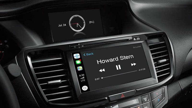
Just as with other applications, the benefit of being part of the CarPlay family is in the safety of the interface. If you want to listen to Howard Stern, get play-by-play from the big game or listen to your favorite music, all you have to do is ask.
Communicate and Be Entertained Safely with CarPlay
If your vehicle doesn’t already have Apple CarPlay, drop by your local mobile enhancement retailer and check out the wide variety of multimedia receivers available. Be sure to bring along your iPhone so you can see just how easy, intuitive and safe Apple CarPlay is.
This article is written and produced by the team at www.BestCarAudio.com. Reproduction or use of any kind is prohibited without the express written permission of 1sixty8 media.