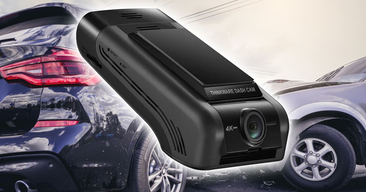
If you are shopping for a premium dash camera with a high-resolution image sensor, the Thinkware U1000 Plus should be on your shortlist. This solution can record video in 4K resolution and is available with a secondary camera to capture what happens behind your vehicle. Let’s take a close look.
Design of the Thinkware U1000 Plus Dash Camera
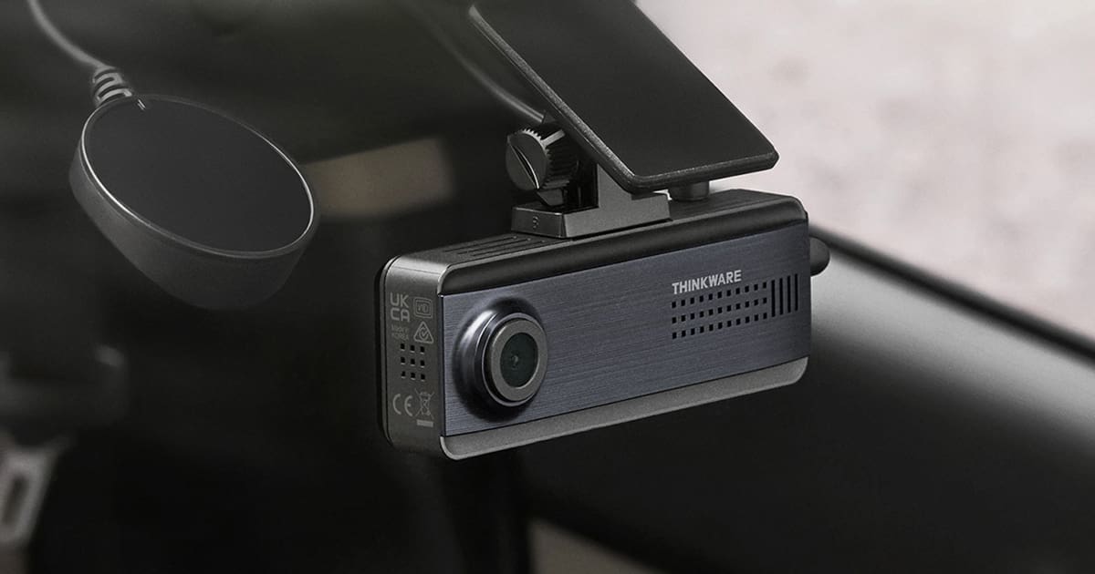
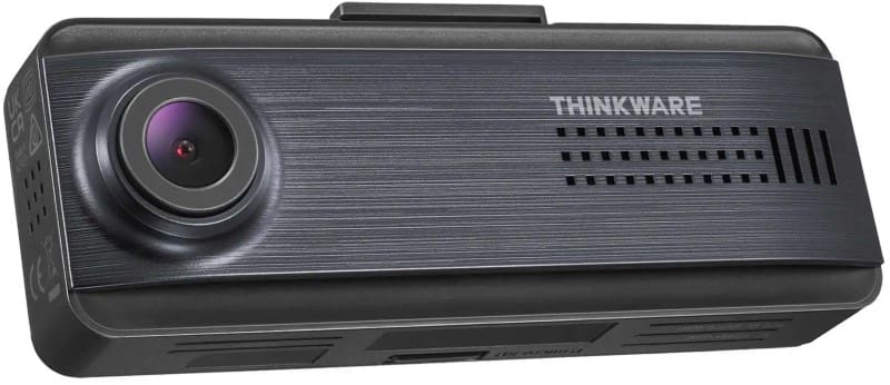
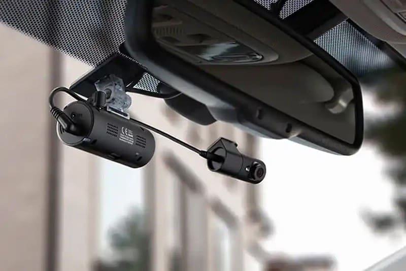
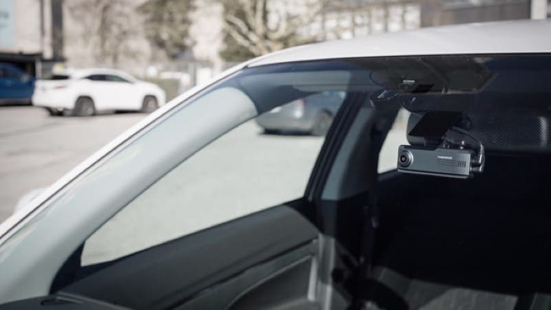
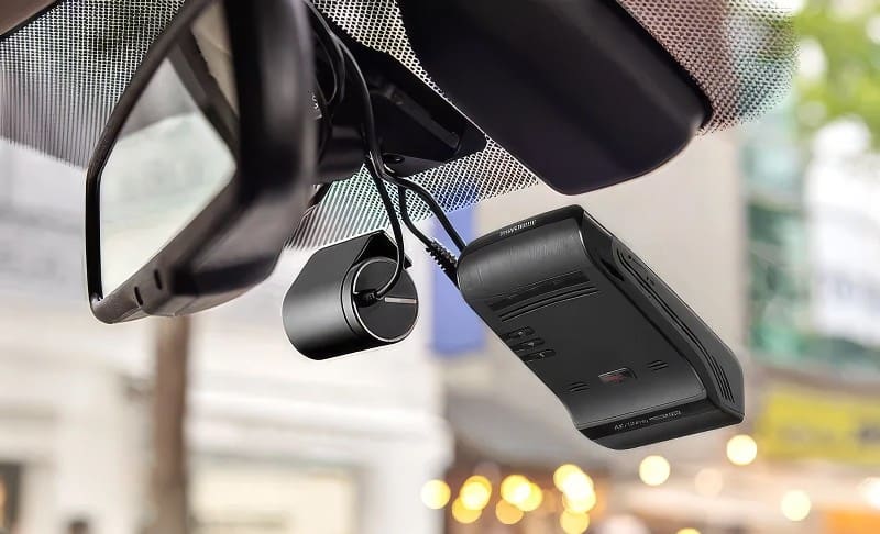
The U1000 Plus is a low-profile camera that mounts at the top of your windshield. Rather than a square or round body, the bulk of the camera sits flat against the glass. This design leaves a lot of clearance for the sun visor and rearview mirror.
The main camera can be tilted up or down to ensure the system works with windshields with varying rakes. The camera body is 4.33 inches tall, 2.55 inches wide and 1.18 inches thick. On the left side of the chassis are power connections, a port for an external radar sensor and the optional rear camera. The rear camera uses a USB connection, so you shouldn’t have issues with RF interference. Thinkware includes a hardwire installation kit with the camera. You can upgrade to the OBD-II power cable if you don’t want any of the wiring in your vehicle modified. This is a wise investment for leased vehicles.
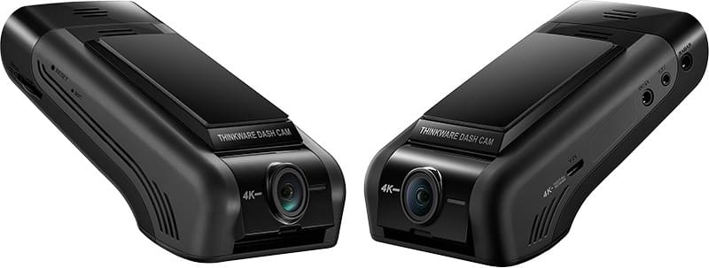
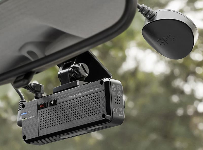
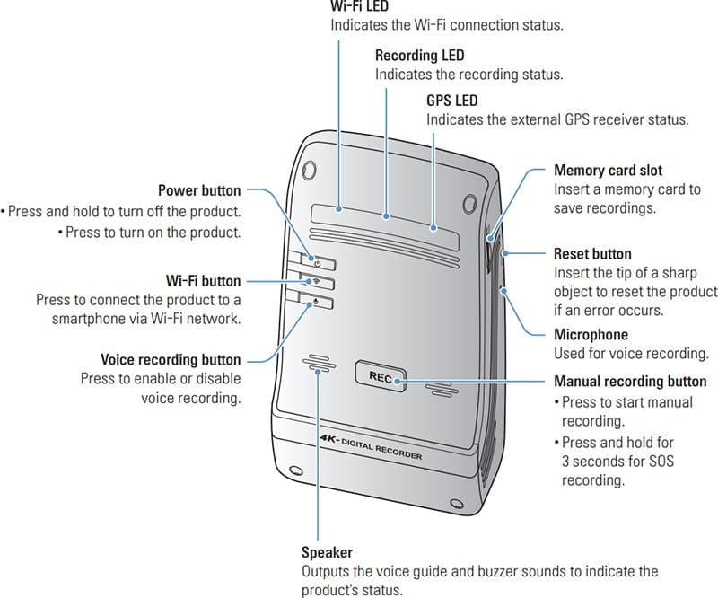
Once installed, the camera body has the manual recording button in the center and the Power, Wi-Fi and voice recording buttons in the upper left corner. LEDs across the top indicate when the unit is on, when Wi-Fi is enabled, and when the GPS receiver has locked on enough satellites to pinpoint your location.
Thinkware Dash Camera Specifications
This camera features a Sony IMX515 STARVIS-Series image sensor that can record at up to 3840 x 2160 pixels at 30 frames per second. It can also be configured to record in 2K mode at 2560 x 1440 pixels at 60 frames per second. The viewing angle is rated at 135.6 degrees, offering a good balance of detail and field of vision.
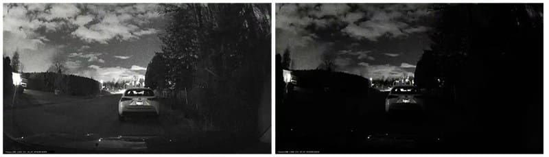
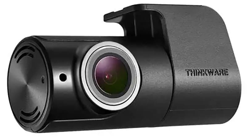
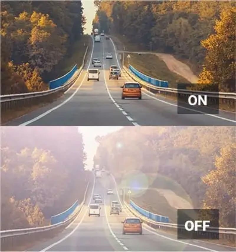
The rear camera features a Full HD-quality image sensor that records 1920×1080 pixels at 30 frames per second. Both the front and rear cameras have a High Dynamic Range (HDR) mode that compresses the light and dark parts of the image to make objects in shadows, or that might be washed out by a bright light source more visible. Low-light performance is further enhanced with Thinkware’s Super Night Vision 3.0. This processing reduces noise when light levels are low to keep videos clear and sharp.
Video files are stored using the HEVC format H.265 to maximize file storage. With the 64GB card included, the system can store up to 151 minutes of video in a dual-camera solution. You can increase the size of the memory card to 512 GB for an incredible 1229 minutes of storage.
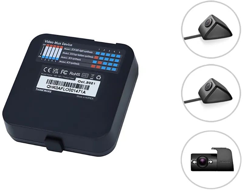
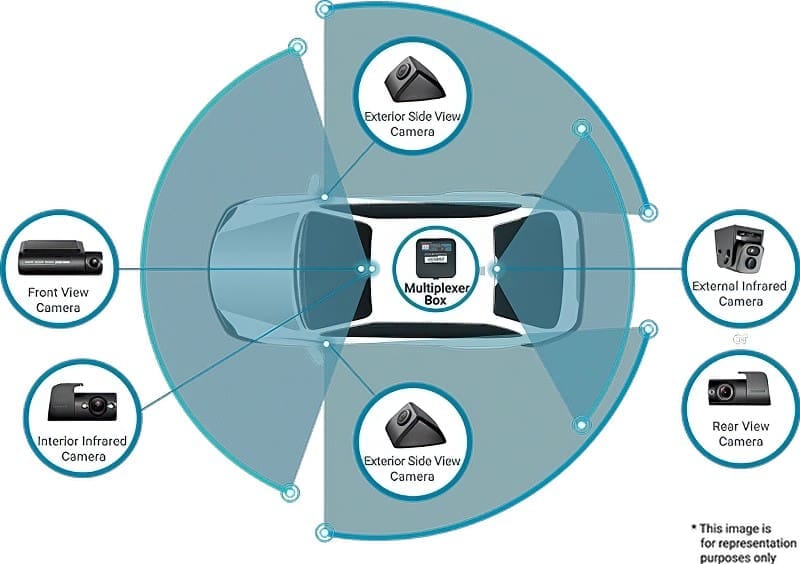
You can upgrade the U1000 Plus to a five-camera system using Thinkware’s optional multiplexer and three additional cameras. This is an ideal solution for taxi, limousine and rideshare applications.
Parking Mode Protection
The Thinkware U1000 Plus includes several parking mode options. In energy-saving mode, the camera only stores video when the onboard accelerometer detects impacts. Motion and Impact mode allows the camera to watch for vehicles or people entering the field of vision along with impact sensing. The camera stores a 20-second video that starts 10 seconds before the event trigger. Time Lapse mode records constantly at two frames per second.
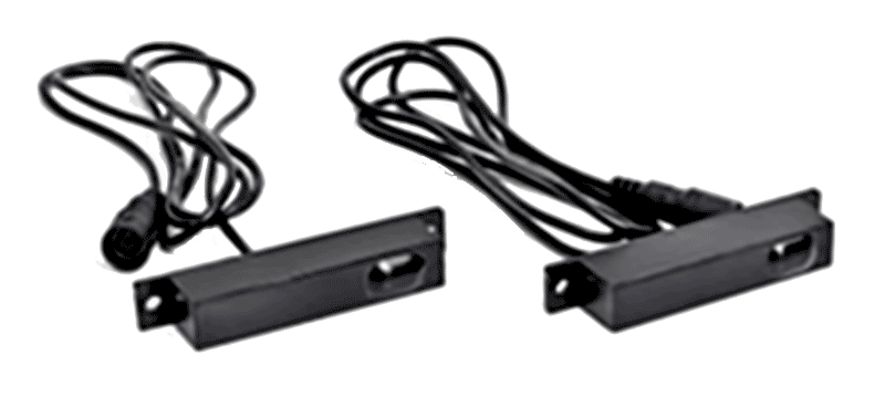
The U1000 Plus can be upgraded with Thinkware’s optional radar module. Rather than monitoring the area in front of the vehicle using the image sensor, the radar sensor detects someone or something approaching. This dramatically reduces current consumption, so there is less draw on the vehicle battery.
Wi-Fi Connectivity
You can use the Thinkware Dashcam Link app on your Android smartphone, iPhone, or tablet to view video files stored on the system. Once connected, your installer can adjust the system settings and fine-tune the viewing angle to ensure maximum coverage.
The Thinkware Connected app gives the U1000 Plus Cloud-based connectivity. If you have a mobile hotspot, or the dashcam can connect to Wi-Fi at your home, you can view what the camera sees on your phone. You’ll also get impact notifications when parked. The vehicle operator can send an emergency message to the registered contact by pressing the REC button on the chassis for three seconds. Parents or business owners can review the vehicle’s operational history to review use and driving behavior.
Advanced Driver Assistance Systems
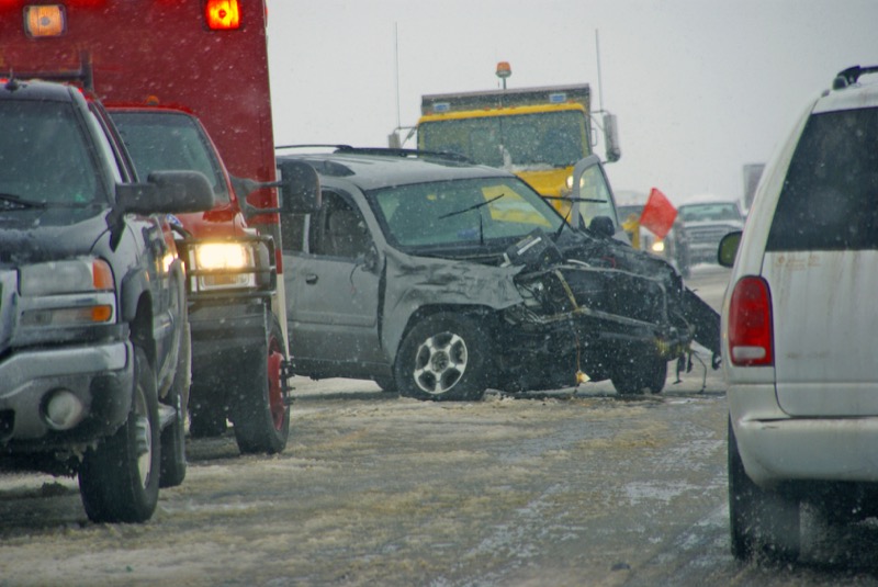
Modern video processing technology allows the U1000 Plus to warn the operating. These Advanced Driver Assistance Systems (ADAS) include Front Vehicle Departure Warnings (FVDW), Forward Collision Warnings (FCWS) and Lane Departure Warnings (LDWS). Notifications about approaching a vehicle too quickly or crossing the lines on the side of the road can help prevent serious accidents.
If you are shopping for a premium dash camera with a high-resolution image sensor, the Thinkware U1000 Plus should be on your shortlist. This solution can record video in 4K resolution and is available with a secondary camera to capture what happens behind your vehicle. Let’s take a close look.
Upgrade Your Vehicle with a Thinkware Dash Camera
We all know that having a dash camera is the best way to protect yourself from fraud and false accusations. It’s also an ideal solution for capturing those “I can’t believe that just happened” moments. When upgrading your vehicle, drop by a local authorized Thinkware retailer and ask about the U1000 Plus system. They can provide you with a quote that includes expert installation.
You can learn more about Thinkware products like the U1000 Plus by visiting their website. Their dealer locator makes it easy to find a retailer near you to help design and install a premium dash camera system.
This article is written and produced by the team at www.BestCarAudio.com. Reproduction or use of any kind is prohibited without the express written permission of 1sixty8 media.