 It may seem as if they should be similar processes, but installing a new source unit, amplifiers and speakers in a car is unlike installing most home audio systems. It is not as simple as plugging things in and hoping they work. Proper integration of your new electronics into modern vehicles and their wiring is getting more and more complicated as complex factory sound systems become more involved. One thing that hasn’t changed, though, is the need to configure the equipment you have selected. Your installer will include this setup time in the cost to install your system. What does system setup and configuration involve? Read on to find out.
Signal-level Adjustments
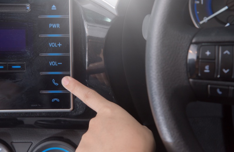
 When it comes to adding an amplifier to your vehicle, the most significant adjustment your installer will make is to adjust the amplifier’s sensitivity or gain control. Amplifiers have these controls so they can be compatible with a variety of different source units with different maximum output voltages.
Amplifiers are relatively simple devices in concept. They take an audio signal from your source unit and increase its voltage so it can drive a speaker. A 100 watt amplifier has to be able to increase a 1 volt signal more than a 4 volt signal to reach the 20 volts required to produce 100 watts into a 4 ohm speaker. The gain or sensitivity control lets us adjust for almost any source unit voltage.
Why Sensitivity Adjustments are Important
If the sensitivity of the amplifier is set too low, you will not be able to get the full power of your amplifier. If it is set too high, then you can drive the amplifier into distortion quite quickly. Too much “gain” can also add noise to the system in the form of hiss. A little extra is OK to allow quiet recordings to be played loudly, but too much is a surefire sign that whoever set up the system did not fully understand gain structure.
System Setup Tools

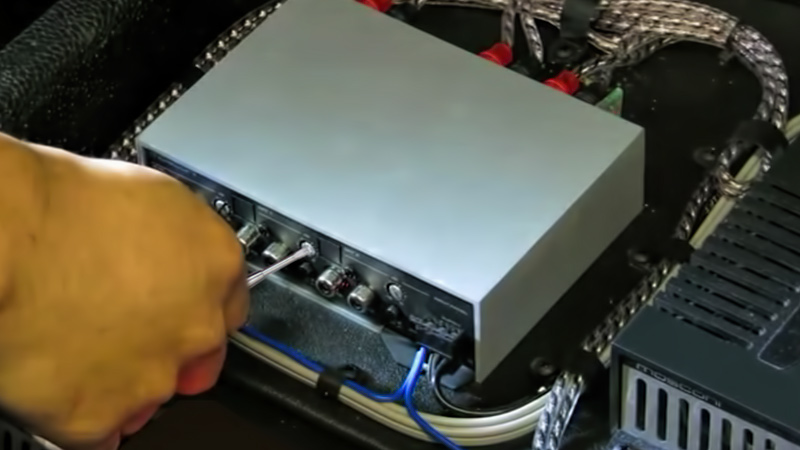
Different shops use different techniques to set gains on amplifiers. Some use an oscilloscope along with a set of test tones. Others use distortion detection devices like the SMD DD-1 or DD-1+. Finally, some installers are quite adept at setting up systems by ear, but that comes with years and years of experience.
As long as the system plays loudly without significant noise or distortion, the settings can be considered correct. If the system runs out of power at half-volume, then it needs some more adjustments.
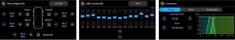
Crossover Adjustments
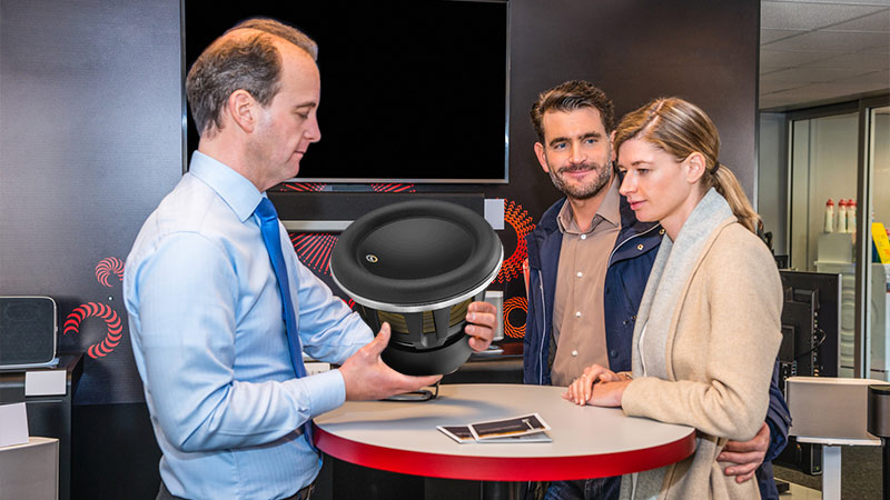
There are two main advantages of adding a subwoofer to an audio system. A subwoofer provides more bass output than a typical set of door speakers could ever hope to produce. The secondary benefit is to relieve the small speakers of their requirement to try to produce bass. This reduction in bass reduces the distance the speaker cones have to move and directly reduces the potential for distortion. Midrange frequencies can be reproduced with improved clarity and at higher levels.
Tying this back to system tuning, how we set the crossovers built into your amplifier is crucial to ensuring that the output of your system blends perfectly between the midrange speakers and the subwoofer. If the crossover points overlap, there can be too much midbass, and the system will sound boomy or “honky.” If the crossover points underlap, the system probably won’t have enough midbass and will sound very dry and flat; the subwoofer can also sound “separated” from the system, reducing the coherence and realism of your music.
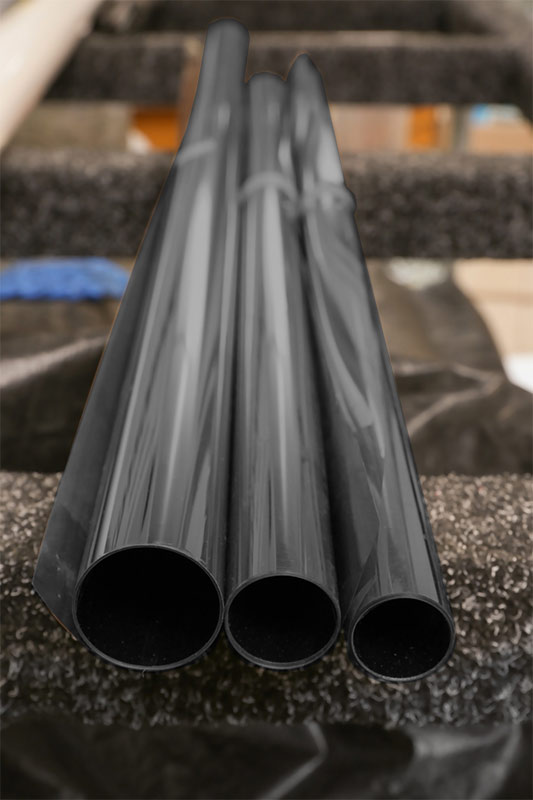
Speaker Polarity Adjustments
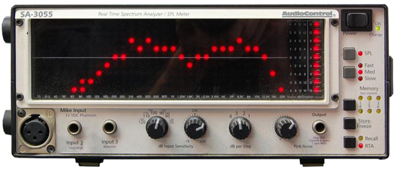
Because each vehicle is different, sometimes the direction a speaker faces requires that we wire it in reverse polarity for the output to combine properly from an acoustical standpoint. This requirement is very common with subwoofers, since they are often pointed in the opposite direction from the smaller interior speakers. Properly trained and equipped installers know how to measure the frequency response of a system and correct for that. In most cases, an audio analyzer is the best choice for setting up a system. These can be stand-alone units from companies like AudioControl and NTI or software-based solutions that work with a laptop, netbook or tablet.
Left-to-right speaker polarity, and the polarity between midrange drivers and tweeters, depends on placement and crossover slopes. These regions deserve analysis before a car leaves the install bay.
Leave It to the Experts
A properly tuned sound system will play louder, last longer and be much more enjoyable to listen to. As you can see from even from this overview, the tools and training required to maximize the performance of even a simple mobile sound system can be expensive and complicated. The staff at your local mobile enhancement retailer should be familiar with these processes and employ them on each installation they perform. Confirming this is part of your process in selecting a retailer that is qualified to work on your vehicle.
This article is written and produced by the team at www.BestCarAudio.com. Reproduction or use of any kind is prohibited without the express written permission of 1sixty8 media.