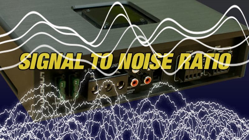
 Most people understand the importance of amplifier power specifications. In most cases, more power is a good thing, that is, until you reach the thermal or suspension limits of the speakers you are using. One specification that is also very important in a mobile electronics amplifier, processor or source unit is Signal-to-Noise Ratio. In this article, we are going to explain what S/N Ratio numbers are and why they are important.
All the Noise, all the Time!
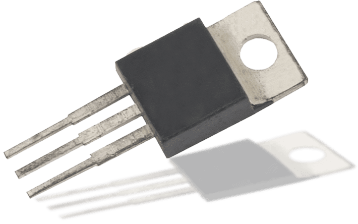 It just so happens that when you pass a signal through any device – like a piece of wire, resistor, capacitor, inductor, transistor or anything else you can think of – a tiny little bit of noise is added to the signal. There are many different kinds of noise. The random motion of electrons bouncing around as they pass through a device causes thermal noise. Higher temperatures result in more noise. Another common noise is Shot Noise. The difference in arrival times of electrons as they cross a barrier or gap between two materials causes Shot Noise. Devices like transistors and diodes, which have different layers of materials inside, are common sources of Shot Noise. There are many more types of noise.
As you can imagine, the amount of noise generated by any one of these devices is minuscule. When you add up a little bit of noise from a bunch of components, then you amplify the resulting signal, the amount of noise in the output of a circuit grows dramatically.
Noise happens in source units, signal processors and amplifiers. Once you add noise to the signal chain, it’s essentially impossible to remove it.
The Sound of Noise
 An easy way to hear what noise sounds like is to connect a set of headphones to your laptop computer and turn the volume up fairly high. You’ll hear a hiss through the headphones. That’s noise. (Note: Please be careful, we want you as an audio enthusiast for life. Take those headphones off before your computer plays a sound and you risk damaging your hearing.)
How We Measure Noise
 There are a few ways to quantify the noise an electronic component creates. One method is to simply state the noise on the output of the device in absolute terms. The measurement could be in volts or watts, and quantifies the amplitude of the noise signal. You won’t see this used to describe audio components, however.
The most common method of quantifying the noise that a product adds to the signal is to compare the noise level to that of the audio signal coming out of the device. Because the difference in these levels can be quite large, we state the ratio of the signal level to the noise level using the decibel (dB) scale. The decibel scale is logarithmic. As such, a difference of 6 dB represents a doubling of the amplitude ratio, 20 dB is ten times the amplitude, 40 dB is 100 times, 60 dB is 1000 times and 80 dB is 10,000 times and so on.
Let us look at a moderate quality amplifier – nothing awesome, nothing disastrous. We see that this fictional amplifier has a S/N Ratio of -82.3 dB when referenced to 1 watt of power output into a 4-ohm load. What does that mean? Well, first, we know that to produce 1 watt of power into a 4-ohm speaker, we need 2 volts RMS of signal coming out of the amp. Our noise level is 82.3 dB quieter than 2 volts. Using an online calculator, that means that the noise produced by this amp is 0.00006918309709189363 times smaller than 2 volts, so it’s about 0.000138 volts. A little more math and that works out to 4.785 nanowatts.
Nope. That isn’t very much noise. And in most cases, you probably can’t hear it.
What if we work hard and find a below-average amplifier? Something with a S/N spec down around 70 dB? If we apply that math to our 2 volts of rated output, we get a noise level of 99.99 nanowatts. Yep, that’s a LOT more watts as compared to the previous example.
Clarifying the Mysterious Signal-To-Noise Ratio
If you look at an amp spec from more than about 10 years ago, or you see a number that is abnormally high, they may be rating the noise level using the maximum output capability of the amplifier as the comparing factor. If we measure an amplifier’s noise output level at 1 watt to be 85 dB, then you increase the amplifier’s output to 10 watts, assuming it doesn’t make any additional noise, the S/N ratio will be -95 dB. If the amp can produce 100 watts with no more noise, the ratio is now -105 dB. There are hundreds of amps that can produce 1000 watts – so that noise ratio measurement would now be -115 dB. When it comes to printing numbers on a gift box, in a brochure or publishing them on a website, being able to say that the S/N Ratio is -115 dB sure looks more appealing than -85 dB.
 The CEA-2006 specification established a standard set of guidelines for S/N Ratio noise measurement. The specification dictates that we measure the S/N Ratio compared to 1 watt of output into a 4-ohm load. A new specification is in the works that will help quantify the adjustment of the sensitivity setting on the amplifier during the measurement process. As it sits, the lower the setting of the amp, the better the S/N ratio measurement will be. Want to confirm this? Next time you are installing an amp, turn the system on with no signal connected to the amp and listen to the speakers. Then turn the amp gain up all the way. You will hear the noise level increase. Please turn the gain back down and shut the system off before proceeding.
Why is the Lack of Noise Important?
How can we quantify the desire not to add noise to our signal? Here is a simple analogy. If you purchased a TV in recent years, you may have heard the expression ‘blacker blacks.’ ‘Blacker blacks’ refers to how dark the screen gets when there is no signal. Blacker is better. When you think about your audio system, a ‘more negative’ S/N ratio means that the noise is quieter than the audio signal. We don’t want to listen to noise. -90 dB is better than -80 dB. Go it? Clear?
There are so many criteria to balance when choosing any car audio product. Power levels, efficiencies, distortion characteristics, features and functions all play an important role. Understanding the meaning of the S/N ratio measurement is very important. We don’t want ANY distortion or noise added to our music, but the laws of physics deny us that luxury. Do your best to choose products that, through careful design and choice of internal components, minimize these negative effects. Your local mobile electronics specialist can help steer you towards some amazing equipment. Drop in and check out what’s new.
This article is written and produced by the team at www.BestCarAudio.com. Reproduction or use of any kind is prohibited without the express written permission of 1sixty8 media.