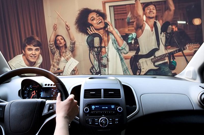
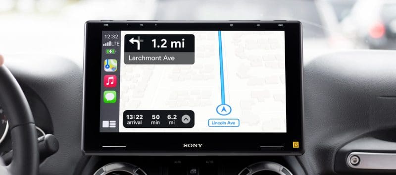
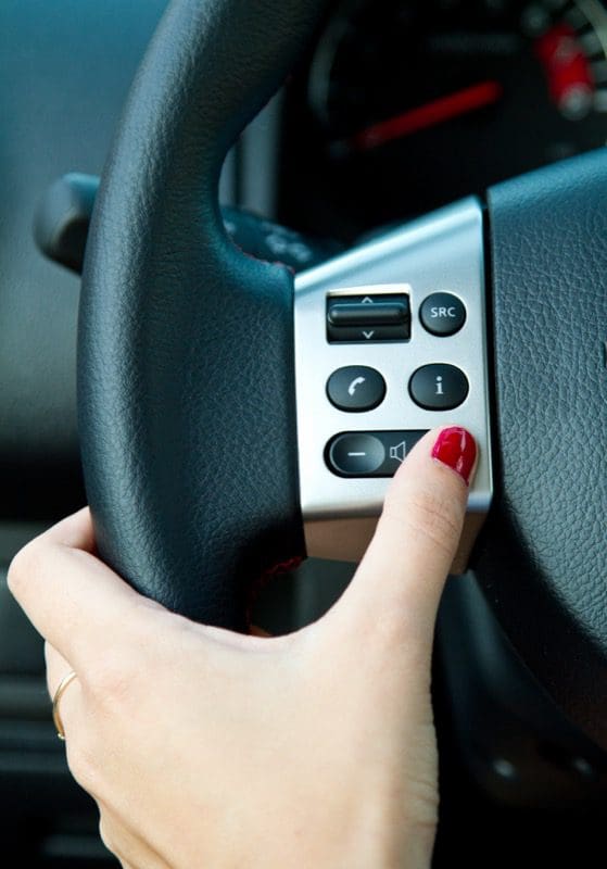
 When you go shopping for a new radio for your car, one of the many questions the product specialist should ask you is whether your existing radio has steering wheel-mounted audio controls. Almost every aftermarket radio has provisions to accept a signal that will give you steering wheel audio control functions like volume, source selection, tracking and power. Here’s how it all works.
Factory Control Functionality
 There are two common types of steering wheel control interfaces. The first is resistive; the second is data. Systems that use resistors often have two wires connected to the switches. Each switch presents a different resistance value when pressed. The factory radio sees these different resistances as different voltages and the computer in the radio responds appropriately. There are usually two wires so a multitude of switches can have well-separated resistance values to ensure functions will never overlap.
A small computer is built into the steering wheel controls switches in vehicles that use data communication for the steering wheel audio controls. This computer has inputs dedicated to each switch and its function. When you press a switch on the steering wheel, the computer sends a digital communication to the computer in the radio. Often, this communication takes place on the vehicle’s CAN data network.
Connection to Aftermarket Radios
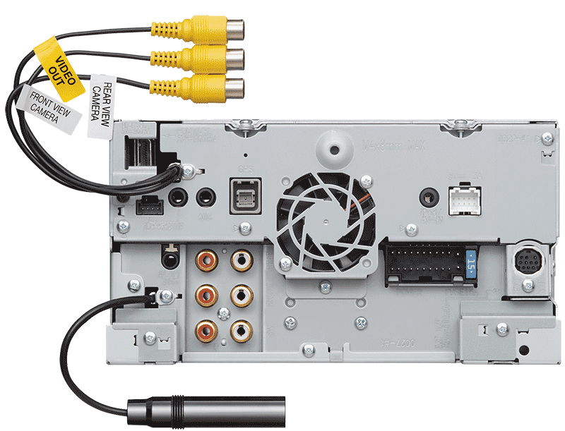
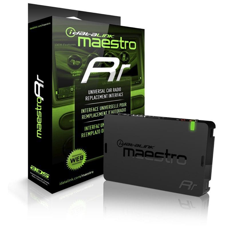 In North America, almost every radio is Steering Wheel Remote Control Ready. Being “Ready” means the radio has a connection on the back to accept a serial data communication signal. The communication language used on the radio connection is not the same as that used in the vehicle. Thus, you will require an interface module to make everything work. Companies like iDatalink, Axxess and Pacific Accessory Corporation (known in the industry as PAC) all offer interfaces that can be programmed to understand and translate the information from the vehicle to something that is compatible with your radio.
Steering Wheel Audio Control Installation
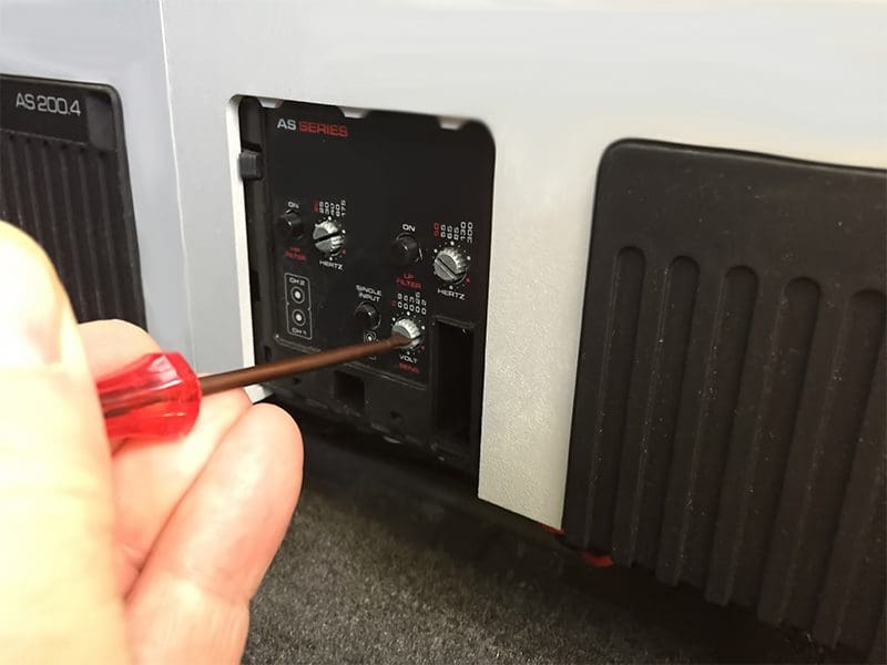
 When your tech is installing the new radio in your vehicle, he has three tasks to complete to make the steering wheel audio controls work. First, he must wire the controls into your vehicle. In many cases, the installer will use a “harness saver” or “wire harness adapter” to connect a set of bare wires to the factory radio plug for power, illumination and speaker wire connections. This adapter usually includes the steering wheel communication wires from the vehicle.
Once the installer completes the electrical connections, the next step is to program the module to understand the commands from the vehicle. Some interfaces have software built into them to recognize commands from the vehicle automatically.
Another method of programming the interfaces uses a website that will allow the installer to select the year, make, model and trim level of the vehicle, and program the interface to recognize the correct commands.
Finally, the interface has to be programmed to send the correct commands to the new radio. Each brand of radio has a set of dedicated and unique command codes.
Additional Options
 Over the past few years, many vehicle owners have chosen to upgrade their factory radios to add Bluetooth audio streaming and hands-free calling to their vehicle. New cars have telephone control buttons on the steering wheel, but older ones don’t. Several of the interface modules have the ability to send different commands to the aftermarket radio, depending on how long you press and hold the steering wheel buttons. For example, a quick tap on the Volume Down button will, of course, turn the volume of the aftermarket radio down. You can have the button programmed so pressing and holding it for a couple of seconds to tell the radio to answer an incoming Bluetooth phone call.
The list of compatible functions varies by vehicle and the make and model of the aftermarket radio.
Custom Applications
 One unique feature of the steering wheel control interface is that your installer could build a set of custom controls for you. Let’s say you are building a custom car, and you want to add a nice sound system. In most applications like this, the builder will install the aftermarket radio in the glovebox, under the seat or in the trunk of the vehicle. But how can you control the radio if you cannot reach the controls? Your installer could mount a set of switches in the center console and then program the switches, through an interface module to control the aftermarket radio.
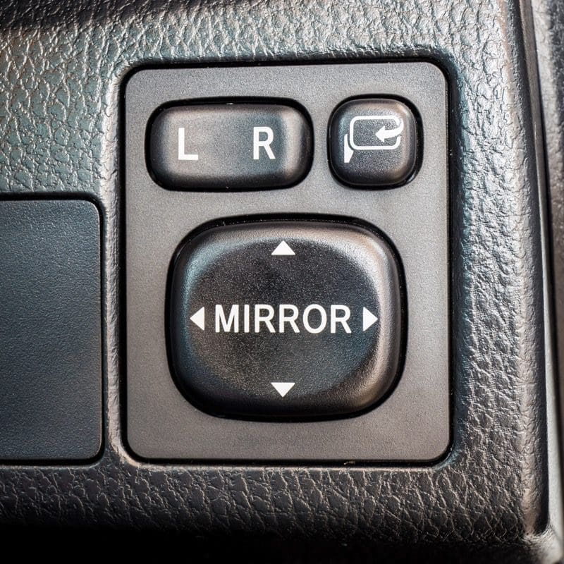
Some installers and fabricators have gotten quite creative with these switch installations. A power mirror adjustment switch, for instance, serves as a great solution for volume and tracking functions.
Your Retailer is Ready to Help
When it is time to install a new radio in your vehicle, drop by your local mobile electronics specialist retailer. They would be happy to show you the latest in car audio source units and explain how they can integrate it into your vehicle.
This article is written and produced by the team at www.BestCarAudio.com. Reproduction or use of any kind is prohibited without the express written permission of 1sixty8 media.