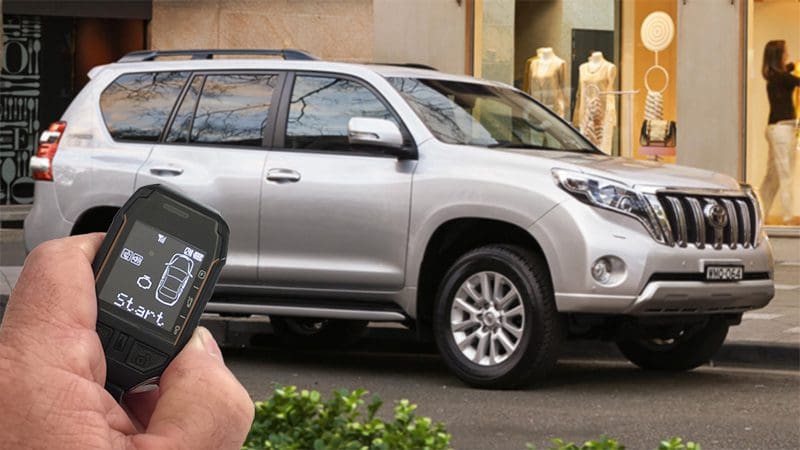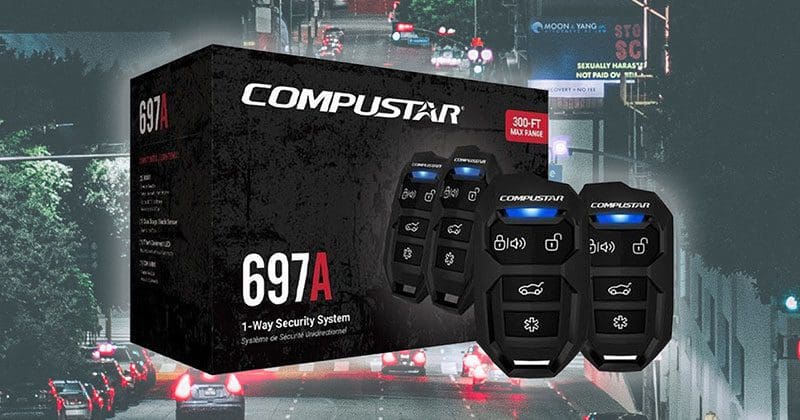
Though best known for its class-leading remote car starters, Compustar is rolling out a new line of vehicle security systems that includes the affordable CS697-A to protect your car or truck. While many vehicle owners believe the security system that comes with their vehicle is adequate, the reality is that those solutions are limited in their capabilities. An aftermarket alarm is the only way to completely protect your vehicle.
Features of the Compustar CS697-A Vehicle Security System
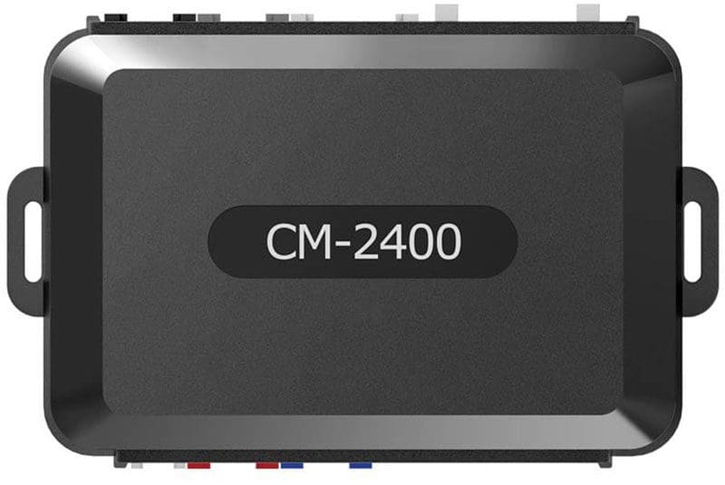
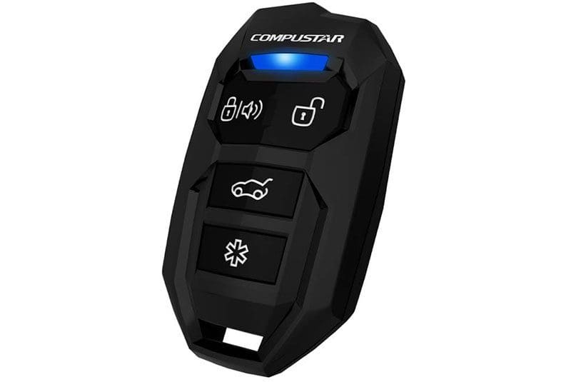
The CS697-A car alarm includes a dual-stage shock sensor, starter disable circuitry and two remote controls. The shock sensor monitors the body of the car or truck for sudden impacts from door dings in a parking lot or an attempt to break a window. Moderate impacts will result in the system honking the vehicle horn and flashing the parking lights. Significant impacts set off the full alarm, flashing the lights and honking the horn for 30 seconds. The system also includes dedicated door monitoring inputs and the ability to monitor the hood and trunk or hatch of your car or SUV. Additional sensors and door switches can be added for commercial vehicles or heavy-equipment applications.
The system includes keyless entry functionality that will let you lock or unlock your doors remotely. Your installer can integrate the 697-A system with the remote trunk or hatch release function to make loading or unloading easier. The system activates the interior dome light for 45 seconds after receiving the unlock command so you can make sure everything inside is safe before you get in. Finally, two auxiliary outputs are provided to control options like a power sliding door or power window control module for added convenience.
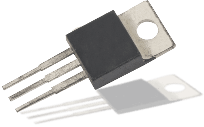
According to the FBI, almost 250,000 vehicles are stolen in the United States every year. To help combat this, Compustar includes its E-LOCK relay in the 697-A. When properly integrated into your vehicle, this relay functions as a stand-alone starter-kill to further complicate the efforts of thieves hoping to steal your vehicle.
Vehicle Protection Upgrade Options
While this vehicle security system provides a solid set of features, just like Compustar’s remote car starters, it’s based around a control unit that’s easily upgradable. A high-output siren can be added to attract additional attention to the vehicle. Likewise, the DAS-II four-in-one sensor is another popular upgrade as it adds a digital tilt/motion sensor with glass breakage detection. If you’re concerned about wheel or catalytic converter theft, DAS-II is a great option.
You can also add the KP2 touchpad that mounts to the inside of your windshield. You can enter a user-defined code by touching the glass to disarm and unlock the vehicle. You can also choose to upgrade to a two-way remote control that will alert you when the alarm is triggered. If you choose a remote upgrade package like the PRO R5 or PRO T13, the proximity unlock function will unlock the doors automatically when you are within about 6 feet of the vehicle.
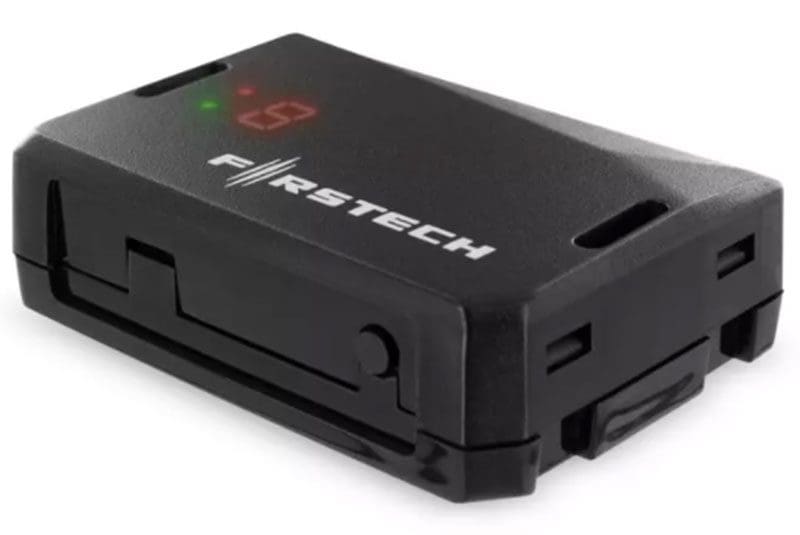
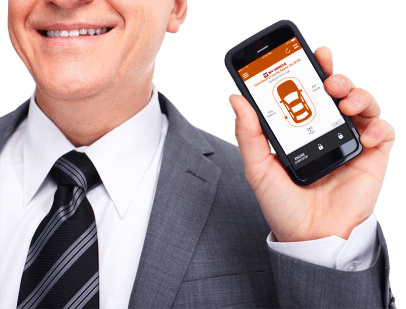
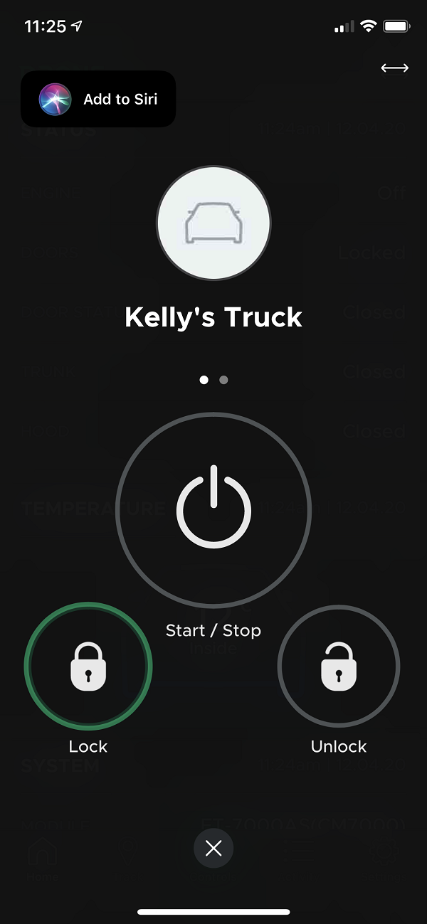
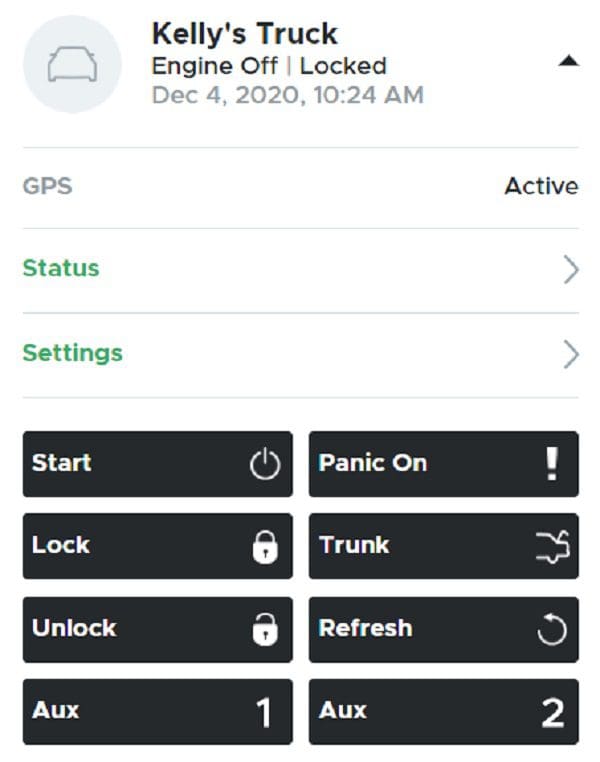
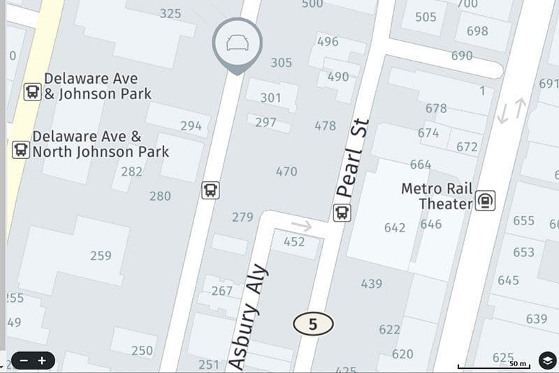
The ultimate upgrade is the Drone telematics system. You can be anywhere on the planet and still receive security warning notifications from your car or truck, so long as your smartphone can access the Internet. Better yet, Drone includes options to add GPS-based features that will send alerts if the car or truck moves while the system is armed or during user-programmable curfew hours. Impact, motion, tilt and glass breakage alerts from the DAS-II sensor are also relayed to your smartphone using the DroneMobile app.

Protect Your Investment with an Aftermarket Car Alarm
In 2019, Ford and Ram pickup trucks were the top two most stolen vehicles in the U.S. While these trucks came with factory-installed security, their popularity made them key targets for thieves. An aftermarket security system adds valuable damage and vandalism protection and a second starter-kill circuit that, when appropriately integrated, makes unauthorized starting of the vehicle nearly impossible.
Drop by your local Compustar retailer today to learn more about the CS697-A and its security and convenience options. You can learn more about Compustar car alarm and remote starter solutions by visiting their website, Facebook Page, Instagram Page or their YouTube channel.
This article is written and produced by the team at www.BestCarAudio.com. Reproduction or use of any kind is prohibited without the express written permission of 1sixty8 media.

 [CC BY-SA 3.0 (https://creativecommons.org/licenses/by-sa/3.0)], via Wikimedia Commons")